Posts

Showing posts from 2010

Diesel Engine Combustion Efficiency

Index Key: ENG048 Author: gerald j ballmann Subject: Diesel engine combustion efficiency. 1) What limits the compression ratio of a diesel engine? 2) What is the best fuel to use in a diesel engine for maximum efficiency? Response #: 1 of 2 Author: daniel n koury jr The compression ratio for a particular engine is limited by how strong the engine block is. Too much pressure (compression) and something will break. The best fuel will also depend on the design of the engine. But as a general rule, the greater the energy content of the fuel, the greater the efficiency (at least in terms of miles per gallon or km per liter). Water has a low energy content and would not make a good fuel for example. Response #: 2 of 2 Author: david r munoz The limits to compression ratio are based on the knock limits of the fuel. Knock is the term used to describe the auto ignition that occurs when a fuel ignites because the pressure in the cylinder is such that combustion occurs. I

Measure Indicated Power in Diesel Engine with Indicator Diagram

Image
The burning of fuel in an engine cylinder (2 stroke or 4 stroke diesel engine) will result in the production of power at an output shaft, some of the power produced in the cylinder will be used to drive the rotating masses of the engine. Typical indicator diagram for a 2 stroke engine is shown in figure below. The area within the diagram represents the work done within the cylinder in one cycle. The area can be measured by an instrument known as 'Planimeter' or by the use of the mid ordinates rule. [On modern engines this diagram can be continuously taken by employing two transducers, one pressure transducer in the combustion space and other transducer on the shaft. Through the computer we can thus get on line indicated diagram and power of all cylinders.] The area is then divided by the length of the diagram in order to obtain mean height. This mean height, when multiplied by the spring scale of the indicator mechanism, gives the indicated mean effective pressures for the cyli

Fuel Injector Testing

Image
Mount he fuel injector in its test rig and connect up the oil supply. Under no circumstances should hands be placed under the injector spray. The high velocity oil jet can penetrate the skin and cause blood poisoning. With the injector priming valve open, operate the hand pump to prime the injector. Once the fuel flows from the priming valve it can be closed. Oil Container Pressure Gauge Shut off valve Pump lever Test pump Injector High Pressure fuel pump Operate the pump rapidly for several strokes. The injector should open with a high pitched chatter and fuel should be emitted in a fine cloud. After the injector opens, check to make sure the pressure does not fall off too quickly. To test for the tightness between the nozzle needle and seat, operate the hand pump slowly to gradually increase the pressure until it is just below opening pressure. Maintain the pressure for a few seconds and ensure injector is not dripping. To test for

How Diesel Engines work

Image
Diesel Engine is a type of internal combustion engine (one from which work is obtained by compression of the fuel within the cylinders themselves) which operates on the constant pressure or diesel cycle principle. Fuel is admitted directly into the cylinder and combustion takes place as a result of the heat of compression. In these engines, gas pressure in the cylinder acts on the piston, forcing it down during the power stroke to drive the crankshaft through connecting rods. The extreme positions reached by the piston correspond to the top and bottom dead center positions (TDC & BDC) of the crank and are so designated. The inside diameter of the cylinder is the bore. The distance traveled between dead centers (TDC &BDC) is the stroke, corresponding volume is the swept volume, or displacement, of the cylinder. The cylinder volume above piston when piston is at TDC is called clearance volume. Similarly the cylinder volume above piston when piston is at BDC is called cylinder v

external electrical connectors broke/corroded

CAUSE OF FAILURE 6...mishandling during installation/removal/testing, water/moisture leaking past injector plug connector, inadequate vehicle maintenance, improper storage. EFFECTS OF FAILURE 6...no firing, intermittant firing, or weak firing of injector due to poor electrical conductivity , poor engine performance, poor fuel economy. engine overheating, potential engine damage, overfueling of other cylinders as 02 sensor reads excess 02 in exhaust and adjusts "rich" to compensate.

injector pintle doesn't fully seat on orifice

CAUSE OF FAILURE 5...fuel additives "baked" on pintle or orifice, weak injector return spring, rust/corrosion internal to injector body. EFFECT OF FAILURE 5...leaking fuel injector, after shutdown fuel leak in affected cylinder (causing hard start), overfueling of affected cylinder with resultant underfueling of remaining cylinders in the "closed loop" system, potential for damage to O2 sensor or "cats".

Body or mechanical joint leak in injector body

CAUSE OF FAILURE 4...Defective manufacturing and testing, overheating of injector from cooling system failure, ignition system failure, incorrect timing, improper "handling" during installation/removal/storage/shipping, etc. EFFECT OF FAILURE 4...High potential for engine fuel fire (dependent on location of leak), poor engine performance, poor fuel economy, potential for engine damage.

Injector windings don't lift pintle, seized pintle, or slow pintle cycling

CAUSE OF FAILURE 3...injector coil windings overheated from cooling system failure or ignition failure, with windings losing their magnetic performance; open (broken) windings; shorted (grounded) windings; seized pintle from internal injector corrosion (engine has set too long without running causing the injector to rust internally, petrol contamination with water, or cycling of injector without fuel flow to act as cooling agent and lubricant). EFFECTS OF FAILURE 3...(A) If injector pintle is "off" the seat...overfueling of affected cylinder with resultant underfueling of remaining cylinders within "closed loop", poor engine performance, poor fuel economy, possible O2 sensor damage, potential engine overheating and engine damage, hard or no start, fuel leaks after shutdown. (B)If injector pintle is "on" the seat...underfueling/no fueling of affected cylinder with resultant overfueling of remaining cylinders with "closed loop" system, poor eng

Injector filters become clogged

CAUSE OF FAILURE 2..."Foreign particles" in fuel tank(s) or fuel lines, or fuel rail. Foreign particles in almost all instances, will be rust. Larger rust particles may be collected within the injector filter, or the fuel filter, and reduce fuel flow. Microscopic rust particles may also pass thru the injector filter, and cause the spray pattern to alter, fuel flow to alter, and/or the injector pintle to not seat properly. This is a common problem on vehicles that have sat unattended, or suffered from lack of routine maintenance. Incorrect fuel tank fuel filter; holes/tears in fuel tank fuel filter; breakdown/degradation of interior wall of fuel supply line; breakdown/degradation of interior wall of fuel injector hose, and rust in the fuel rail. EFFECTS OF FAILURE 2...the injectors leak at the pintle and/or the spray pattern is altered, and/or the fuel flow is altered. Lack of engine power from underfueling; potential for engine overheating; remaining injectors/cylinde

Fuel Injectors Work

The TBI system took the place of the carburetor as governmental automobile pollution standards increased , as well as a simultaneous increase in consumer requirements for greater fuel economy. In the TBI system, a throttle body sits atop the engine in the location where the carburetor use to reside. The throttle body in fact looks very much like a carburetor, however it performs very much differently. Located within the throttle body are one or two injectors (depending on the vehicle). When the engine is started, a continuous spray of pressurized fuel is discharged thru the injectors, into the intake manifold, and from there on to the cylinders for combustion. The injectors in the TBI system are always open, and spraying fuel when the engine is on. They do not pulse on and off. Furthermore, the one or two injectors are supplying fuel to every cylinder collectively, as did the carburetor, but with much greater precision. While the TBI system, and the advances in engine managem

Engine speed governor

I have built a small diesel generator but the mechanical governor does not seem to respond quick enough.I would like to build an electronic governor that will also have overspeed shutdown protection. I have built a couple of simple electronic controllers for my biogas projects from schematics but I am certainly not an electronics tech. The engine is from a refridgeration unit that was electroniclly controlled so their is a sensor over the flywheel for speed siginal to the controller. If anyone out their can help with this project it would be very much appreciated.

Crankshaft Bearing Failure

My 11 year-old 1000-hour 38 HP Yanmar 3JH2E Diesel on my 36 foot sailboat experienced crankshaft bearing failure. The center bearing disintegrated while the other two bearings remained in perfect condition. The circumstances were the prop shaft became entangled in lobster fishing gear during a passage through the Cape Cod Canal. In order to make any headway to keep control and get to a safe anchorage, I had to apply full emergency power to a heavily overloaded engine. The center crankshaft bearing failed, while the other two survived. Because the crankshaft was heavily scored, the engine was a total loss, and needed replacement. The insurance surveyor, claimed that this was a "mechanical failure due to latent defect" "or possibly faulty maintenance" and recommended that the claim be denied, despite clear evidence that the prop and shaft were entangled. I would like your opinion of the possibility that heavy lugging at high power settings caused he
Maxi Fly Wheel

Image
Description: Peugeot Sport 106 maxi flywheel. This is a homoligated flywheel for 106. Banned for Super 1600 but is fine to use under Group A6. This flywheel is very light and not suitable for gearboxes with long final drives. As you will struggle on touring stages (hill starts). However the pickup of the engine in the stage is chalk and cheese compared to the standard flywheel.

Trans Brace

Image
I believe in maximizing the rigidity of the block / transmission assembly. We had to reconfigure Honda's brace to fit properly with the Moroso oil pan. Details like this are important to building a long-lasting combination.

Twin Disk cm

Image
Lots of pieces fit into small spaces with this package. Note the sculpting to reduce flywheel mass and the small diameter of the pressure plate, disks and floaters. This set-up is extremely lightweight and capable of handling a lot of abuse, including shifts over 10K.

Header Flange

Image
Note that the header primary pipes are configured to work with our raised port roofs. Oil heater? We'll make sure there's some separation here before installation. I'm also raising secondary pipes and collector about 1.5" for better in-vehicle ground clearance, which is important on the streets of Ft. Worth.

HDon't be mislead by the picture, but it's imperative that the header (and intake) gaskets do not hang in the way of the flow. If you don'eader Gasket

Image
Don't be mislead by the picture, but it's imperative that the header (and intake) gaskets do not hang in the way of the flow. If you don't trim the gaskets, you're potentially sacrificing any possible gains from porting. We trim the gaskets to be approximately .050" larger all the way around the port. This gasket is situated ahead of the flange on the studs, producing the illusion that the openings are much larger than the ports.

Hytech Header

Image
Checking for fitment on our "killer" header from John at Hytech. Note that he configured it for AC clearance. This header is the veteran of many dyno pulls on similar 2-liter engines we've built, so it's a known quantity.

Block Fittings

Image
We're using two breather tanks on this high-revving engine. The block fittings are the same ones we sell, with the anti-siphon tubes for increased efficiency in separating oil. Note the sealant that's standard issue on the threads.

Balancer TDC Mark

Image
Prior to installation, I always mark the harmonic balancer 180 degrees opposite the TDC mark to facilitate setting the valves. Note that this is a stock (neutral-balanced) ITR balancer we're using. Always use a new crank bolt for the installation.

Torquing Cam Bolts

Image
Torque the cam bolts to factory specs. Do not use an impact to tighten the bolts... Note our fixture that inserts pins between the cam gears, locking them together at a "straight-up" position for torquing and installing the timing belt.

Vtec Dowel

Image
Before the final installation of the cam caps, make sure to put the oil dowel and "O" ring in the head under the center cap. Yes, we lube the hell out of the camshafts.

Rocker Lube

Image
We use moly-lube on the rocker arms, to insure that there will be as little friction as possible with the cam's new lobes. Keep observers will note that these rockers have been treated to new altered-radius wiper pads, which are furnace brazed to the rocker bodies and ground to work properly with the cams' lobes.

Clicking Clearance

Image
If you look closely, you can see the heads of the exhaust valves behind the intakes in this photo. This particular head/valve/cam combination has .030" "clicking clearance". Sort of scary knowing that if one side is just a touch too quick, or too slow, the valves will lock and the engine will be history when the piston "closes" them.

Piston To Valve

Image
It's also mandatory that you check piston to valve clearance with any non-stock combination you assemble. If you "assume" it'll be OK because you know of someone else running the combination, you're asking for trouble. I use the same fixture we use on the flow bench to place the indicator on the valve retainer.

Block Dowels

Image
We machine the dowel holes in the heads deeper than Honda does, but for those of you milling blocks, heads, and or using thinner-than-stock head gaskets, it's essential to shorten the locating dowels by at least the amount of material removed to prevent the head from sitting "up" at the corners. Failure to do so can result in oil-leaking head gaskets.

Lost Motion Devices

Image
We use ITR lost motion devices in any head running cams with more than .425" valve lift. Note the high pressure lube on the top of the valve stems.

Assembling Head

Image
Assembling these heads with the springs positioned "deep" in the head requires a lot of patience, or a fixture like this designed for the task.

Spring Seats

Image
In order to accommodate the springs' installed heights, we machined .025" off the bottom of the stock Honda spring seats. This view shows the difference between our modified spring seat and the stocker's thickness. We coat the underside of these seats for increased lubricity prior to installation.

Spring Tension

Image
We test each and every spring for installed pressure and open pressure.

Valve Springs

Image
Here's a reality check for you. At the left is our newest spring for the B series engines. It's stable to 12,000 rpm. It specs out at 70psi on the seat with 222 nose pressure at .550" lift. Price is $400.00 per set. At the right is a Pro Stock spring that's used by all the top running teams. It's made of titanium. it costs $400.00 (per spring) and it's capable of controlling valve motion at 12,000 rpm. It's a throw away item after 8 runs. Pressure......you could put one of these atop your car's shock absorbers and chunk the springs. If import racing survives, you'll be seeing this sort of thing in the future, as racing becomes more lucrative and competitive.

Rrocker Arm Mod

Image
In this photo, you can see the material removal necessary to achieve retainer-to-rocker arm clearance. Any grinding marks must travel length-wise on the rocker to eliminate possible stress-risers.

Rocker Retainer Clearance

Image
We have to use retainers that set-up .060" higher than stock. This can lead to retainer-to-rocker arm contact. It's essential that the clearance between the retainer and the rocker arm be at least .040". We check this clearance on every head we rework and assemble, as failure to do so can result in catastrophic engine damage

Endyn Mod Manifold

Image
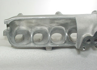
Here's the semi-finished manifold interior. The runner roofs are now shorter than the floor, by exactly the ports' dimensional differences. Note the inverted radius we achieve at the upper runner-to-plenum intersect. With the plenum side in place and a 64mm throttle body, this manifold will out-flow the best individual throttle body combination we've ever tested. At .500" valve lift the head/manifold combination will flow 349cfm @ 28"H20 with equally impressive mid-lift numbers.

Manifold Prep

Image
When I tell people that these manifolds weigh as much as 2 lbs less when we're finished, they think I'm kidding. Believe it. We rather dramatically alter the runner volumes, cross sectional areas, window shapes, and plenum entry geometries in this rework.

Stock Manifold

Image
Our manifold preparation for one of these engines begins with a Skunk2 casting. We cut the plenum in half to facilitate the porting and plenum reshaping.

Centerless Valve Grinding

Image
We grind all the valves with the most accurate centerless valve facing machine available to achieve face run-out measurements of less than

Milling Cylinder Head

Image
After calculating the engine's compression ratio, it was determined that we needed to remove some more material from the head's deck surface to obtain the volume necessary.

Ccing Piston

Image
We place one of the pistons in a steel sleeve of the exact cylinder bore diameter. The depth is just enough to clear the dome's highest point. We measure and record the distance from the top of the cylinder to the intake quench pad of the piston. Red grease is used to make a fluid-tight seal between the piston and the sleeve.

Ccing Hambers

Image
Once all the port tweaking is complete, it's time to CC the combustion chambers. We use a spark plug like will be run in the engine, as well as the valves fitted for each cylinder.

Dummy Cylinder

Image
For valid flow test results, the head must be situated atop a dummy cylinder of the exact diameter that will be used on the actual engine application. The length of the cylinder must be at least 1.5 times the engine's stroke.

Flow Bench

Image
After all the porting, the head and manifold are analyzed and tweaked on the flow bench. It's mandatory that the flow rates from cylinder to cylinder are essentially the same (less than .5% deviation) at all valve lift points. The manifold is an extension of the intake ports, so it must be in place when flowing this side of the head. Exhaust pipes and header flange must be similarly used on the other side to obtain valid data.

Checking Camshaft Fitment

Image
Prior to finishing the head, we always install the camshafts that the engine will use. If the cams spin freely and the clearances check out to be within spec, everything's good. If there's any problem, it's essential that the proper clearances be achieved, or broken camshafts will result. This is something that absolutely MUST be checked. If you fail to, don't let me hear you crying when a camshaft snaps.

Water Pump

Image
We're using a new ITR water pump that's had it's vanes trimmed a bit to slow water flow at extreme rpm levels. Note that we're also using a magnetic

Moroso Pick Up

Image
he bottom end is close to finished with the installation of a "trimmed" (for proper oil pan fitment) ITR windage tray and the Moroso oil pick-up. Note that the pan uses studs for mounting rather than the conventional stud/bolt arrangement.

Endyn ITR Oil Pump

Image
Next we install one of our modified ITR oil pumps to insure that the engine will have an adequate and dependable supply of oil.

Deck Clearance

Image
The best way to measure deck clearance is with a depth micrometer. We decked this block to achieve a clearance of - .002", meaning that the flats of the quench pads are .002" below the block's deck surface.

Rotational Torqu

Image
It's important to check the amount of break-away torque, as well as the constant torque required to rotate the lower end assembly. Break-away should be checked with the pistons at mid-stroke and shouldn't exceed 10 ft lbs. Rotational torque shouldn't exceed 6 ft lbs.

z10 Engine

Image
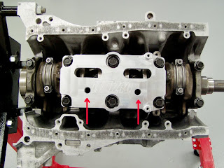
Be Before installing the girdle assembly, we machine a couple .625" holes in it, accompanied by a lot of "sculpting" on the crankshaft side to help route oil into the sump more efficiently. We torque the main caps to the factory specs for a GSR/I using new bolts.

Pistons In Block

Image
All four pistons in their new homes. The posts on either side of the cylinders are visible in this shot.

Rod Bolt Stretch

Image
I measure the free length of the rod bolts prior to torquing and afterward, I measure the stretch to insure that all's within the bolt's specs. Note that I don't have the center main caps (or the girdle) installed while installing the piston/rod assemblies, as it makes for a lot more working room.

Installing Pistons

Image
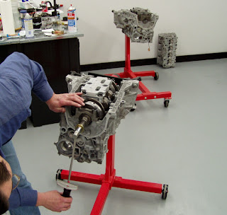
Installing pistons is simple when everything is prepared correctly. With a good ring compressor that's correctly squared with the block's deck, all it takes is a nudge from the hammer's handle. I always put the crank's rod journals "down" when installing pistons.

wd40 On Rings

Image
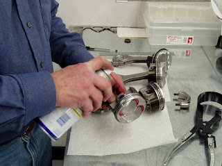
I use WD40 on the piston skirts and rings prior to installing them in the block. This provides an adequate degree of early lubrication, while still permitting enough friction for a fast ring break-in. Not the scissors-style ring compressor that we use. It's not terribly expensive and it sure beats the hell out of the band-style compressors.

Piston Pin Clips

Image
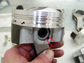
When assembling the pistons to the rods, I always make sure the ends of the pin-retaining clips are on either side of the notch in the pin bore. This insures that they have maximum surface area to "bite". Note that I've also wiped all traces of moly-lube from the sides of the pin bores in an attempt to insure than none will reach the cylinder walls, possibly impeding early ring seating.

Rods Pistons

Image
As you can see, we've assembled the rods to the pistons. The bearings that were fitted and labeled will be inserted next.

Piston Skirt Ceramic

Image
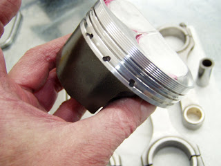
Here's a view of the skirts on the pistons. As discussed in the article, the piston to wall clearance was too large, so we coated the skirts with a high-pressure ceramic coating and block-sanded it to achieve the correct contact patch and clearance we desired. This coating also has a high coefficient of lubricity, so not only did it "save" our block and pistons, but it should help out by reducing friction a bit.

Development Piston Dome

Image
Here's a view of the dome on the pistons I'm using. This was a set of "development" pistons from early-on in of the strutted skirt program. Note the stake marks, which show the centerline of the valves. You can also see that the scribed valve circumference is well inboard of the edges of the valve reliefs, causing me to lose about a full CC of dome displacement. The boss always gets the throw-away pieces!

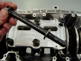
Main Bolt Lube

Image
Don't forget to lube the main bolt threads, as well as the areas above and below the washer so torque readings will be accurate. If you're wondering why my hands look dirty, this moly-lube is the culprit.

Main BearingLube2

Image
With the crank in the block, it's also important to lube the bearings in the main caps. A moderate film of lube is all it takes.