Posts

Showing posts from February 14, 2010

Milling Cylinder Head

Image
After calculating the engine's compression ratio, it was determined that we needed to remove some more material from the head's deck surface to obtain the volume necessary.

Ccing Piston

Image
We place one of the pistons in a steel sleeve of the exact cylinder bore diameter. The depth is just enough to clear the dome's highest point. We measure and record the distance from the top of the cylinder to the intake quench pad of the piston. Red grease is used to make a fluid-tight seal between the piston and the sleeve.

Ccing Hambers

Image
Once all the port tweaking is complete, it's time to CC the combustion chambers. We use a spark plug like will be run in the engine, as well as the valves fitted for each cylinder.

Dummy Cylinder

Image
For valid flow test results, the head must be situated atop a dummy cylinder of the exact diameter that will be used on the actual engine application. The length of the cylinder must be at least 1.5 times the engine's stroke.

Flow Bench

Image
After all the porting, the head and manifold are analyzed and tweaked on the flow bench. It's mandatory that the flow rates from cylinder to cylinder are essentially the same (less than .5% deviation) at all valve lift points. The manifold is an extension of the intake ports, so it must be in place when flowing this side of the head. Exhaust pipes and header flange must be similarly used on the other side to obtain valid data.

Checking Camshaft Fitment

Image
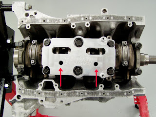
Prior to finishing the head, we always install the camshafts that the engine will use. If the cams spin freely and the clearances check out to be within spec, everything's good. If there's any problem, it's essential that the proper clearances be achieved, or broken camshafts will result. This is something that absolutely MUST be checked. If you fail to, don't let me hear you crying when a camshaft snaps.

Water Pump

Image
We're using a new ITR water pump that's had it's vanes trimmed a bit to slow water flow at extreme rpm levels. Note that we're also using a magnetic

Moroso Pick Up

Image
he bottom end is close to finished with the installation of a "trimmed" (for proper oil pan fitment) ITR windage tray and the Moroso oil pick-up. Note that the pan uses studs for mounting rather than the conventional stud/bolt arrangement.

Endyn ITR Oil Pump

Image
Next we install one of our modified ITR oil pumps to insure that the engine will have an adequate and dependable supply of oil.

Deck Clearance

Image
The best way to measure deck clearance is with a depth micrometer. We decked this block to achieve a clearance of - .002", meaning that the flats of the quench pads are .002" below the block's deck surface.

Rotational Torqu

Image
It's important to check the amount of break-away torque, as well as the constant torque required to rotate the lower end assembly. Break-away should be checked with the pistons at mid-stroke and shouldn't exceed 10 ft lbs. Rotational torque shouldn't exceed 6 ft lbs.

z10 Engine

Image
Be Before installing the girdle assembly, we machine a couple .625" holes in it, accompanied by a lot of "sculpting" on the crankshaft side to help route oil into the sump more efficiently. We torque the main caps to the factory specs for a GSR/I using new bolts.

Pistons In Block

Image
All four pistons in their new homes. The posts on either side of the cylinders are visible in this shot.

Rod Bolt Stretch

Image
I measure the free length of the rod bolts prior to torquing and afterward, I measure the stretch to insure that all's within the bolt's specs. Note that I don't have the center main caps (or the girdle) installed while installing the piston/rod assemblies, as it makes for a lot more working room.