Posts

Showing posts from September 19, 2009

Uniflo and loop scavenging

Image
2 stroke engines with an exhaust valve mounted in the cylinder head are known as uniflow scavenged engines. This is because the flow of scavenging air is in one (uni) direction. MAN B&W MC series uniflow scavenged engine Some 2 stroke engines do not have exhaust valves; As well as scavenge ports in the cylinder liner, they are fitted with exhaust ports located just above the scavenge ports. As the piston uncovers the exhaust ports on the power stroke, the exhaust gas starts to leave the cylinder. When the scavenge ports are uncovered, scavenge air loops around the cylinder and pushes the remaining exhaust gas out of the cylinder. This type of engine is known as a loop scavenged engine. Note that the piston skirt is much longer than that for a uniflow scavenged engine. This is because the skirt has to seal the scavenge and exhaust ports when the piston is at TDC. Although simpler in constru

coolind the engine

Image
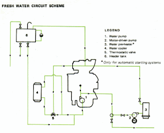
Although there is an abundance of free sea water available, marine diesel engines do not use it directly to keep the hottest parts of the engine cool. This is because of the corrosion which would be caused in the cooling water spaces, and the salts which would be deposited on the cooling surfaces interfering with the heat flow. Instead, the water circulated around the engine is fresh water ( or better still, distilled water) which is then itself cooled using sea water. This fresh water is treated with chemicals to keep it slightly alkaline ( to prevent corrosion) and to prevent scale formation. Of course, if distilled water, which some ships can make from sea water using evaporators, is used then there is a reduced risk of scale formation. The cooling water pump which may be engine driven or be a separate electrically driven pump pushes the water around the circuit. After passing through the engine, where it removes the heat from the cylinder liners, cylinder heads, exhaust valves a

2stroke cycle

Image
It may surprise you to learn that the biggest diesel engines in use operate on the two stroke principle. If you have experience of the two stroke petrol engine you will know that it causes more pollution and is less efficient than a 4 stroke petrol engine. This is because oil is mixed with the petrol to lubricate the crankshaft bearings, and a lot of unburnt petrol/oil/air mixture is discharged to the atmosphere. To learn more about the 2 stroke petrol engine cycle click here . The two stroke Diesel engine does not mix fuel or oil with the combustion air. The crankshaft bearings are lubricated from pressurised oil in the same way as a four stroke engine. The two stroke cycle is so called because it takes two strokes of the piston to complete the processes needed to convert the energy in the fuel into work. Because the engine is reciprocating, this means that the piston must move up and down the cylinder, and therefore the crankshaft must revolve

2stroke crosshead engines

Image
The 2 stroke crosshead engine works on exactly the same principle and cycle as the 2 stroke trunk piston engine. The disadvantages of the two stroke trunk piston engine are that although it has a low overall height, lubricating oil splashed up from the crankcase to lubricate the liner can find its way into the scavenge space, causing fouling and a risk of fire. There is also the likelihood of liner and piston skirt wear, allowing air into the crankcase. This can supply the required oxygen for an explosion should a hot spot develop. The crankcase oil must have additives which can cope with contamination from products of combustion, and the acids formed during combustion due to the sulphur in the fuel. The majority of 2 stroke engines encountered at sea are of the "crosshead" type. In this type of engine the combustion space (formed by the cylinder liner, piston and cylinder head), and the scavenge space are separated from the crankcase by the diaphrag

Viscosity measurement

Image
INTRODUCTION For efficient and complete combustion, residual fuel must be heated before it is burnt. For correct atomisation in the cylinder, the fuel must be at the correct viscosity. If the viscosity is too high, the fuel droplets will tend to be too large and will take too long to absorb the heat energy from the compressed air before they start to burn. This will lead to late and incomplete combustion, lack of power, afterburning and damage or fouling to liner, piston crown, exhaust valve and turbocharger. If the viscosity is too low, then the droplets will be too small and combustion will tend to be early and incomplete because the fuel droplets will not have penetrated far enough into the cylinder to find sufficient oxygen to burn completely. This again will cause damage and fouling. Because residual fuel is a complex blend of heavy asphaltenes blended with lighter distillates, and will vary in its make up, to ensure that the fuel is maintained at the correct viscosity for inj

Testing

Image
Stability and Compatibility Before taking on bunkers it is advisable to take a sample from the suppliers tanks and test it for stability and compatibility. If the fuel is unstable it is likely to stratify in the tanks and form asphaltenic sludges. If it is incompatible, then although it may be stable on its own, when mixed with existing bunkers in the ships tanks, it may form sludges. This is why fuel should be bunkered into empty tanks whenever possible. A small sample of the fuel is heated to 50°C to encourage instability. A sample of the preheated mixture is placed on chromatographic paper and dried in a small oven. The resultant spot is compared against reference samples. In the case of a test for compatibility the two fuels are mixed in the same proportions as would be found in the bunker tanks and the procedure repeated. Water The water test for fuel oil is similar to that for lubricating oil. A sample of the fuel (5ml) is dilut

sampling

Image
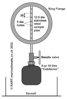
When taking bunkers, a representative sample of the fuel oil delivered should be given to the ship by the supplier. It is not a good idea to accept a sample in a sealed container, without knowing its source. The supplier will often use a flow proportional automatic continuous sampler, which, as its name suggests, will take a sample of the fuel as the the fuel is pumped on board. Before bunkering commences, the sampler is set to the quantity of fuel to be delivered, the bottles connected and the sampler sealed. The Chief Engineer or his representative will be asked to witness the setting and sealing of the sampler. At the end of bunkers, the sample bottles are sealed, again witnessed, and signed. One of the bottles is given to the ship; this should be retained on board for at least 3 months in case of dispute over the bunker quality, when the sample can be sent for independent analysis. Flow Proportional Automatic Continuous Sampler The vessel may want to carry out its own on boa

Refining

Image
The residues that make up residual fuels come from several refinery processes. In the first instance the fuel is heated and fed into the atmospheric distillation column where the lighter hydrocarbon molecules are distilled off as gases, gasoline, kerosene and gas oil, leaving about 50% of the crude as residue. Some of this residue is fed into the vacuum distillation column where it will be further processed to produce vacuum gas oil, waxy distillates and a residue. This residue can form part of the blend in marine bunkers or can be fed into thermal crackers. Here, under high pressure and temperature more light hydrocarbon molecules form and are removed as light distillates. Also the heavy gas oil from the vacuum distillation column may be subjected to catalytic cracking where as a result of chemical reaction yet more light hydrocarbon molecules are formed and separated into even lighter distillate fractions. The residues from all these processes can be blended with a variety of disti

What is Homogenisation?

Image
Homogenise: a : to reduce to small particles of uniform size and distribute evenly usually in a liquid b : to reduce the particles of so that they are uniformly small and evenly distributed. Residual fuel oil can be described as a combination of heavy asphaltene agglomerates and bituminous matter blended with lighter distillates. Sometimes the heavier constituents are not dispersed evenly in the fuel and stratification can occur. Sludge is produced by precipitation of suspended asphaltenes from the fuel – a common occurrence triggered by the high carbon content in heavy marine fuels. When the fuel is injected into the engine the lighter factions burn first; the asphaltene agglomerates are very slow burning and sometimes do not burn completely, leading to deposits of heavy carbons and ash on pistons, exhaust valves and turbochargers. If these heavy, relatively large particles of fuel can be broken down into smaller droplets, then the surface area is increased an