Posts

Showing posts from September 18, 2009

visatron OMD

Image
Most text books only cover the operating principle of the older type of Graviner oil mist detector. A lot of engines are fitted with the Visatron oil mist detector manufactured by Schaller automation. A venturi driven by low pressure compressed air draws the samples from the crankcase compartments. The samples from the crankcase pass through an oil droplet separator which removes any droplets of oil by centrifugal force before passing across the measuring track of the oil mist detector. A receiving photodiode converts the intensity of an infra red beam of light from an infra red light emitting diode into an electrical signal which is fed to the electronic evaluation unit. As the opacity of the sample increases so the intensity of the infra red beam being measured by the receiving photodiode will decrease. This will produce a lower electrical signal. To prevent the infra red filters becoming soiled by the crankcase samples and affect

Reducing risks of crankcase explosions

Image
Crankcase explosions which are violent and cause the maximum damage are thought to be caused by turbulent flame fronts having enough room to accelerate to sonic velocities thus raising the crankcase pressure high enough in a very short time to have serious consequences. The large two stroke engines currently being built have a crankcase volume approaching 600m 3 with overall lengths of 23 metres. Experience has shown that in two similar engines having crankcase explosions, one where the ignition source was close to the centre of the engine caused minimum damage, whilst the other, where the ignition source was at one end of the engine suffered a severe explosion in which crankcase doors were blown off. Therefore it should be possible to limit the consequences of an explosion which travels the length of the crankcase by subdividing the crankcase into separate compartments. However this might not be as simple as it first sounds. To begin with the subdividing bulkhead would have

Oil mist detectors

Image
There are two methods of oil mist detection, Obscuration and Light Scatter . The earlier forms of oil mist detector used an obscuration type detector, the most well known type being the early Graviners. Schaller use obscuration in their Visatron range of OMDs. Light scatter is a modern method of oil mist detection used by QMI and the Latest Graviner Mk6 OBSCURATION The older type of obscuration type of detector consists of two parallel tubes of equal size, each having a photoelectric cell at one end which generates an electric current directly proportional to the intensity of the light falling on its surface. Lenses are fitted to seal the ends of each tube but allow light to pass. Two identical beams of light from a common lamp are reflected by mirrors to pass along the tubes onto the cells which are then in electrical balance. The samples drawn from the crankcase are drawn in turn along the m

Detecting crankcase explosion

IACS Rules state that for an unmanned engine room the main engine must be fitted with EITHER an oil mist detector of an approved type OR main bearing temperature monitors. A manned engine room does not require any crankcase monitoring equipment to be fitted. Bearing temperature monitors can be fitted not only to the main bearings, but also to the bottom end bearing where the temperature is transmitted to a static pick up device from the revolving transmitter once per revolution. Some schools of thought claim that bearing temperature detection is not reliable enough using only one probe per bearing, and that the temperature should be monitored at several points around the bearing. However, although the majority of crankcase explosions are caused by bearing failure, there are other sources, esp. piston/ liner overheating in trunk piston engines, and monitoring of this should also be considered. MAN B&W, as well as using oil mist detectors and main bearing temperature

Crankcase relief valves

REGULATIONS The provision of crankcase explosion relief valves for marine diesel engines is an international safety requirement stemming from two sources, IMO SOLAS Chapter II-1 and IACS Unified Requirements M9 and M10. Summarising, the requirements that relate to explosion relief valves are: i. Crankcases for engines having a cylinder bore greater than 200mm and above or having a crankcase gross volume exceeding 0.6m 3 are to be provided with explosion relief valves. ii. Crankcases for engines having a cylinder bore not exceeding 250mm are to be provided with at least one explosion relief valve at each end of the engine. If an engine has more than eight crank throws an additional valve is be fitted at the middle of the engine. iii. Crankcases for engines having a cylinder bore greater than 250mm but not exceeding 300mm are required to have at least one crankcase explosion relief valve at each alternate crankthrow

Crankcase relief valve testing

Image
FLAME ARRESTORS AND SHIELDING The intention of the requirement to shield the valve discharge was to reduce the possible danger to personnel from flame emission. However explosion testing has shown that whilst a flame arrestor will work satisfactorily when shielding is not fitted, when shielding is fitted, the energy from the discharge is focussed in one direction, and there will be an emission of flames during an explosion. The fitting of shielding also reduces the effective outflow area of a valve. Since July 2002 it has been a Lloyds Register rule requirement to fit flame arrestors and to test the relief valve with any proposed shielding to be fitted to the valve when installed on the engine. A test procedure for new crankcase relief valves has been developed over the past four years by MAN B&W, The Physical Test Institute in the Czech Republic , Hoerbiger, and various classification socie

Retensioning

Image
Medium speed four stroke engines and small two stroke engines use a simple method of checking and adjusting chain tension. The tension is checked by turning the engine so that the longest side of the chain is the slack side. (this is usually when the engine is running astern). After stopping the engine, the chain is then pulled back and forward by hand, and the transverse movement should be between ½ and 1 link. Adjustment is carried out by tightening or slackening the adjustment nuts on the tensioner; see diagram. On larger engines, the method described above becomes increasingly difficult to carry out, so the tension is adjusted automatically by using the compression of a spring to give the correct chain tension. This negates the need for measuring the play in the longest side of the chain when slack (½ - 1 link). The engine is continuously turned in the ahead direction (so that the longest side of the chain is tight). The nuts are slackened off

Renewing the chain

Image
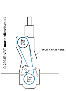
The camshaft chains will have to be replaced when their elongation reaches 1% or after 15 years. The reason for placing a limit on it’s elongation is that as the chain gets longer the pitch increases and is not matched to the wheel teeth, and continued use would result in excessive wear. The chains are replaced one at a time. This is so that the connected chain can be used to turn the engine whilst the new chain is pulled round. To change a chain on a large 2 stroke engine, the chain is slackened off at the tensioner. The top chain case cover is removed, and one of the chains is split at the point indicated. see here on how to split the chain. The new chain is attached to the old chain with a temporary link, and as the engine is turned, the old chain is pulled out of the engine, the new chain is fed in. Once the new chain has been joined, the process is repeated for the second chain and the chain retensioned. The

chain elongation

Image
Students sometimes have difficulty in visualising the effects of the elongation of a timing chain on the timing of the camshaft. This model may help in understanding what happens. It should be made clear from the start that timing chains do NOT stretch, The factor of safety is too high. However, they wear on the bushings and rollers, and this causes elongation and thus a change in the pitch of the chain. For the model, I used bicycle parts, two large wheels of 42 teeth and a smaller 21 tooth wheel for the jockey on the tensioner. Two chains were used; a brand new chain with a pitch of 0.5 inch (12.7mm) and an old worn chain. The percentage elongation between old and new chains is about 2.5% which is way above the max allowable on an actual engine of 1%, but because my model is not to scale, will show the effects more clearly. It will be noticed that a series of 29 links have been painted red and white on both chains. This is to highlight the difference in length and also t

The Piston

Image
Pistons for medium speed trunk piston engines which burn residual fuel are composite pistons; i.e the crown and the skirt are made of different materials. The crown is a heat resisting steel forging which may be alloyed with chromium, molybdenum and nickel to maintain strength at high temperatures and resist corrosion. It is dished to form a combustion chamber with cutouts to allow for the valves opening. The topland (the space between the top ring and the top of the piston) may be tapered to allow for expansion being greater where the piston is hottest. The skirt can either be a nodular cast iron or forged or cast silicon aluminium alloy. Aluminium has the advantage of being light, with low inertia, reducing bearing loading. However because aluminium has a higher coefficient of expansion than steel, increased clearances must be allowed for during manufacture. This means that the piston skirt clearance in the liner is greater than that for cast iron when running at low loads.

Fuel Pump

Image
Medium speed four stroke engines are equipped with jerk type fuel pumps, one for each cylinder. A plunger operated by a cam reciprocates in a barrel. The plunger has a helix machined into it which also forms a vertical groove and an annular groove at the base of the helix. The barrel is located in the pump body which has spill ports, connected to the suction side of the pump, drilled so that they are above the top of the plunger when the cam is on the base circle. The plunger is keyed to a sleeve which has a gearwheel (pinion) machined into it. The pinion meshes with a rack which can rotate the plunger relative to the barrel. The rack is connected to the engine governor. As the plunger moves upwards in the barrel, injection will commence once the plunger has closed off the spill ports and the pressure builds up. As soon as the helix or scroll passes the spill ports the pressure above the plunger will immediately drop, even though the