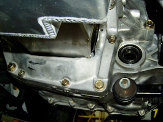
I believe in maximizing the rigidity of the block / transmission assembly. We had to reconfigure Honda's brace to fit properly with the Moroso oil pan. Details like this are important to building a long-lasting combination.
Lots of pieces fit into small spaces with this package. Note the sculpting to reduce flywheel mass and the small diameter of the pressure plate, disks and floaters. This set-up is extremely lightweight and capable of handling a lot of abuse, including shifts over 10K.
Note that the header primary pipes are configured to work with our raised port roofs. Oil heater? We'll make sure there's some separation here before installation. I'm also raising secondary pipes and collector about 1.5" for better in-vehicle ground clearance, which is important on the streets of Ft. Worth.
Don't be mislead by the picture, but it's imperative that the header (and intake) gaskets do not hang in the way of the flow. If you don't trim the gaskets, you're potentially sacrificing any possible gains from porting. We trim the gaskets to be approximately .050" larger all the way around the port. This gasket is situated ahead of the flange on the studs, producing the illusion that the openings are much larger than the ports.
Checking for fitment on our "killer" header from John at Hytech. Note that he configured it for AC clearance. This header is the veteran of many dyno pulls on similar 2-liter engines we've built, so it's a known quantity.
We're using two breather tanks on this high-revving engine. The block fittings are the same ones we sell, with the anti-siphon tubes for increased efficiency in separating oil. Note the sealant that's standard issue on the threads.
Prior to installation, I always mark the harmonic balancer 180 degrees opposite the TDC mark to facilitate setting the valves. Note that this is a stock (neutral-balanced) ITR balancer we're using. Always use a new crank bolt for the installation.
Torque the cam bolts to factory specs. Do not use an impact to tighten the bolts... Note our fixture that inserts pins between the cam gears, locking them together at a "straight-up" position for torquing and installing the timing belt.
Before the final installation of the cam caps, make sure to put the oil dowel and "O" ring in the head under the center cap. Yes, we lube the hell out of the camshafts.
We use moly-lube on the rocker arms, to insure that there will be as little friction as possible with the cam's new lobes. Keep observers will note that these rockers have been treated to new altered-radius wiper pads, which are furnace brazed to the rocker bodies and ground to work properly with the cams' lobes.
If you look closely, you can see the heads of the exhaust valves behind the intakes in this photo. This particular head/valve/cam combination has .030" "clicking clearance". Sort of scary knowing that if one side is just a touch too quick, or too slow, the valves will lock and the engine will be history when the piston "closes" them.
It's also mandatory that you check piston to valve clearance with any non-stock combination you assemble. If you "assume" it'll be OK because you know of someone else running the combination, you're asking for trouble. I use the same fixture we use on the flow bench to place the indicator on the valve retainer.
We machine the dowel holes in the heads deeper than Honda does, but for those of you milling blocks, heads, and or using thinner-than-stock head gaskets, it's essential to shorten the locating dowels by at least the amount of material removed to prevent the head from sitting "up" at the corners. Failure to do so can result in oil-leaking head gaskets.
In order to accommodate the springs' installed heights, we machined .025" off the bottom of the stock Honda spring seats. This view shows the difference between our modified spring seat and the stocker's thickness. We coat the underside of these seats for increased lubricity prior to installation.
Here's a reality check for you. At the left is our newest spring for the B series engines. It's stable to 12,000 rpm. It specs out at 70psi on the seat with 222 nose pressure at .550" lift. Price is $400.00 per set. At the right is a Pro Stock spring that's used by all the top running teams. It's made of titanium. it costs $400.00 (per spring) and it's capable of controlling valve motion at 12,000 rpm. It's a throw away item after 8 runs. Pressure......you could put one of these atop your car's shock absorbers and chunk the springs. If import racing survives, you'll be seeing this sort of thing in the future, as racing becomes more lucrative and competitive.
In this photo, you can see the material removal necessary to achieve retainer-to-rocker arm clearance. Any grinding marks must travel length-wise on the rocker to eliminate possible stress-risers.
We have to use retainers that set-up .060" higher than stock. This can lead to retainer-to-rocker arm contact. It's essential that the clearance between the retainer and the rocker arm be at least .040". We check this clearance on every head we rework and assemble, as failure to do so can result in catastrophic engine damage
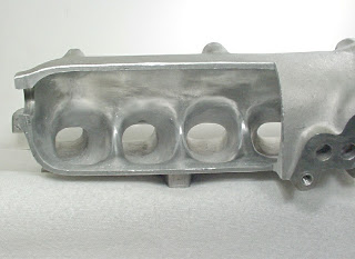
Here's the semi-finished manifold interior. The runner roofs are now shorter than the floor, by exactly the ports' dimensional differences. Note the inverted radius we achieve at the upper runner-to-plenum intersect. With the plenum side in place and a 64mm throttle body, this manifold will out-flow the best individual throttle body combination we've ever tested. At .500" valve lift the head/manifold combination will flow 349cfm @ 28"H20 with equally impressive mid-lift numbers.
When I tell people that these manifolds weigh as much as 2 lbs less when we're finished, they think I'm kidding. Believe it. We rather dramatically alter the runner volumes, cross sectional areas, window shapes, and plenum entry geometries in this rework.
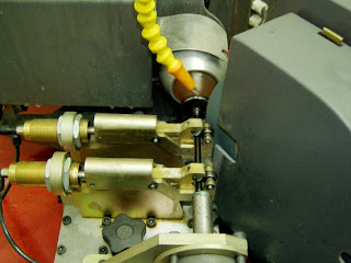
Our manifold preparation for one of these engines begins with a Skunk2 casting. We cut the plenum in half to facilitate the porting and plenum reshaping.