Posts

Showing posts from January 30, 2010

wd40 On Rings

Image
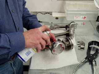
I use WD40 on the piston skirts and rings prior to installing them in the block. This provides an adequate degree of early lubrication, while still permitting enough friction for a fast ring break-in. Not the scissors-style ring compressor that we use. It's not terribly expensive and it sure beats the hell out of the band-style compressors.

Piston Pin Clips

Image
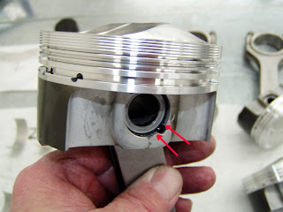
When assembling the pistons to the rods, I always make sure the ends of the pin-retaining clips are on either side of the notch in the pin bore. This insures that they have maximum surface area to "bite". Note that I've also wiped all traces of moly-lube from the sides of the pin bores in an attempt to insure than none will reach the cylinder walls, possibly impeding early ring seating.

Rods Pistons

Image
As you can see, we've assembled the rods to the pistons. The bearings that were fitted and labeled will be inserted next.

Piston Skirt Ceramic

Image
Here's a view of the skirts on the pistons. As discussed in the article, the piston to wall clearance was too large, so we coated the skirts with a high-pressure ceramic coating and block-sanded it to achieve the correct contact patch and clearance we desired. This coating also has a high coefficient of lubricity, so not only did it "save" our block and pistons, but it should help out by reducing friction a bit.

Development Piston Dome

Image
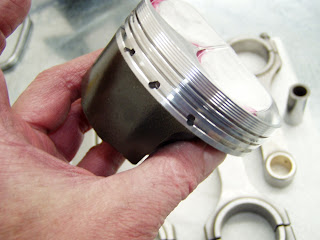
Here's a view of the dome on the pistons I'm using. This was a set of "development" pistons from early-on in of the strutted skirt program. Note the stake marks, which show the centerline of the valves. You can also see that the scribed valve circumference is well inboard of the edges of the valve reliefs, causing me to lose about a full CC of dome displacement. The boss always gets the throw-away pieces!

Main Bolt Lube

Image
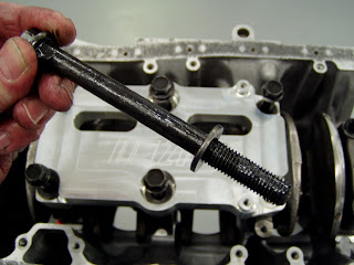
Don't forget to lube the main bolt threads, as well as the areas above and below the washer so torque readings will be accurate. If you're wondering why my hands look dirty, this moly-lube is the culprit.

Main BearingLube2

Image
With the crank in the block, it's also important to lube the bearings in the main caps. A moderate film of lube is all it takes.

Main Bearing Lube

Image
It's important to use put a good film of lubricant on the main bearings prior to installing the crank. Note that I've stamped the main bearing code into the pan rail so it's easy to read. Many blocks from Honda have codes that are damned near impossible to discern, so I "fix" them at every opportunity.

Plasti Gauge

Image
This picture shows the Plastigage strip on #1 and #2 main journals. Our calculations on bearing thickness were right on the money, and as you can see, the plasti-gauge clearly shows that we have .0015" clearance.

Fitting Rod Bearings

Image
Here's a picture of our crude fixture for holding the crankshaft during final bearing fitment for the rods. It's wood, so it can't mar the cranks finish and we clamp it to the table top so torquing the bolts doesn't rotate the fixture (or the rods) during the Plastigage operation. It sure beats the hell out of doing this in the block. The rods and bearings are marked for their respective journals after we've achieved the desired bearing clearances.

Correct Hone Finish

Image
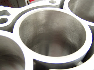
This close-up of the a cylinder shows the correct hone finish. This finish is very smooth to the feel as you run a finger down the bore, but it's coarse when you pull your finger back up. You can see just how small the chamfer is in this picture. Also visible is the upper cylinder "post" in the water jacket at the lower right side.

Chamfer

Image
You can see the small chamfer we use at the tops of the cylinders to "encourage" the rings to go into the cylinders. If the chamfer is excessive, the recess it creates under the head will trap large numbers of hydro-carbons and degrade the combustion efficiency. The small "lines" you see are tiny shiny spots left by the dial-bore gauge when measuring the cylinder ID's.

Crank Shaft

Image
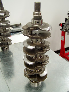
I picked this particular crankshaft for the engine because it's bearing codes worked best with those of the block and the rods. The bearings we'll use are in the "middle" of Honda's thickness chart, rather than "all over the place" in colors. This is a personal preference of mine and we do the same thing with every engine we build.

B20 Engine Block

Image
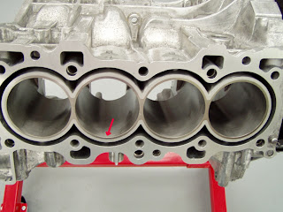
Here's that old B20 block, exhibiting it's acid-eaten finish. Note the posts on the intake side (major thrust axis) of the block. These will support the cylinders under the high loads this engine will be seeing. When we prepare blocks, all the water, oil gallery, and crankcase access plugs are removed.

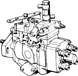
Robert Bosch type VE Diesel injection pump

Image
For many home mechanics the diesel injection pump is a bit of a mystery. The Bentley and Haynes repair manuals doesn't describe its internals, because it's not serviceable except by a few diesel specialists. Learning some basics of how it works and what its internals are could be of interest to the diesel owner, and the knowledge certainly can't hurt when troubleshooting fuel injection problems, even if one isn't about to take the pump apart. The purpose of the fuel injection pump is to deliver an exact metered amount of fuel, under high pressure, at the right time to the injector. The injector, unlike in a gasoline engine, injects the fuel directly into the cylinder or a prechamber connected to the cylinder. The VE in the name of the Bosch pump used in the VW diesels and many other small diesel engines stands for "Verteiler", which is German for distributor or divider. The other common kind of injection pump is the inline p...